Nutzen Sie STL TO STEP für perfekte Produkte

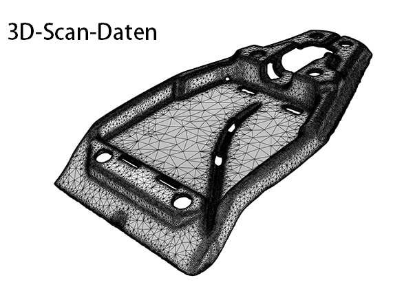
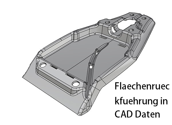
Flächenrückführung von 3D Scan’s

Flächenrückführung von Punktewolken

Flächenrückführung von STL in STEP
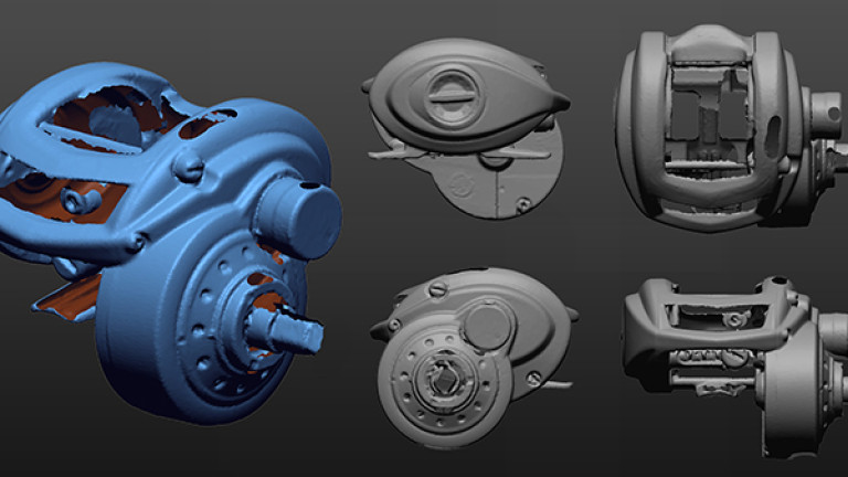
Flächenrückführung oder auch Remodellierung genannt bedeutet für uns den manuellen Aufbau von CAD-Daten, die auf Punkten einer Simulation oder eines 3D-Scans basieren (stl Datei). So erschaffen wir CAD-Daten, die im 3D-Druck, im FEM-Bereich oder auch im Werkzeugbau sehr wichtig sind. Wir haben langjährige Erfahrung in der Umwandlung von stl in step Datein und beraten Sie gerne!

Details zur Flächenrückführung der Mako GmbH
Remodellierung bedeutet die Neuerstellung von Konstruktionsdaten auf Basis von Punktwolken (stl Datein), die durch Simulationen oder mit 3D-Scans erstellt wurden.
Die bestehenden Geometrien werden in der Punktwolke erfasst. Jedes einzelne Element wird hierbei manuell nachgebildet und anschließend zu einem neuen Volumenkörper (Step Datei) zusammengeführt.
Elemente lassen sich mit parametrischen Eigenschaften anlegen. Jeder Schritt in der Konstruktion wird in der Historie festgehalten.
Freiform-Flächen erstellen wir auf der Punktwolke separat neu.
Hierbei wählen wir ein Flächenelement so aus, dass die neu modellierten Bereiche mit Größe möglicher Präzision der Punktwolke entsprechen. Wir erreichen so kleinstmögliche Toleranzen.
Durch dieses Vorgehen erreichen wir höchste Präzision- für alle Bereiche der Industrie.
Differenzierung zwischen STL und STEP
Verschieben Sie die Pfeile, um die Daten vor und nach der Remodellierung zu sehen
Konvertieren Sie Ihre 3D-Scandaten von STL in STEP. Setzen Sie auf Mako-Technics:
Anwendungen für STL to STEP

Industrielle 3D-Modelle

2D-Zeichnungen

Teilemodelle

3D-Druckdateien und -Teile
Wer ist Mako-Technics?
Mako-Technics ist eine führende Marke der Mako GmbH (1998) mit Sitz in Deutschland. Wir bieten unseren Kunden weltweit exzellente Dienstleistungen im Bereich 3D Reverse Engineering. Beispielhafte 3D-Modellierungen und präzises Remodeling zeichnen uns aus.
Hervorragende Mitarbeiter mit großer Erfahrung, eine starke technische Führung und strategische Partnerschaften mit Kunden, Herstellern und Softwareentwicklern bringen Mako-Technics seit Jahrzehnten stetig wachsenden Erfolg.
Diese Grundlagen ermöglichen es uns, weiterhin erstklassige Dienstleistungen rund um die Umwandlung von STL in STEP Datein anbieten zu können und unsere technologische Führungsposition erfolgreich zu behaupten. Unser Know-How ist Ihr Mehrwert.
Vertrauen auch Sie auf unsere Erfahrung. Machen Sie Mako-Technics zu Ihrem strategischen Partner.
Wie können wir Ihnen helfen?

3D-Scan zu CAD
Wir sind Experten bei der Remodellierung in optimal strukturierte CAD-Dateien.

STL umwandeln in STEP
Einen 3D-S can Ihres Objekts stellen wir Ihnen gerne zur Verfügung. Auf Ihren Wunsch hin wandeln wir dieses von STL in STEP um.
3D-Scan in CAD
Autodesk
Wir verwenden Autodesk, um die Leistung in der realen Welt mithilfe eines digitalen Modells im Designprozess zu visualisieren, zu simulieren und zu analysieren.
SolidWorks
Wir erstellen native SolidWorks-Dateien und bieten unseren Kunden das native Datenformat als *.sw-Dateien an. Die Daten können direkt beim Kunden geöffnet werden.
Catia
Mako-Technics verwendet CATIA V6, um Stil und Form des Modells zu optimieren. Kohärente Modelle werden in ihre physischen Formen umgewandelt.
DesignX
If you avail Mako-Technic’s services, we can effortlessly transform your STL 3D scan to STP using Design X. We can recreate complex geometry.
Creo
Wir generieren die Dateien in Creo und bieten Ihnen das native Datenformat als *.creao-Dateien an. Die Daten können direkt beim Kunden geöffnet werden.
Siemens NX
Unsere Ingenieure können mithilfe des robusten und effizienten Siemens NX eine Rückwärtsanalyse durchführen und ein genaues und präzises Duplikat liefern.
2 Möglichkeiten für STEP Datein aus STL Daten
Je nach Anforderung konvertieren wir aus ihrer stl Datei zwei Arten von Step Modellen. Dabei entscheiden Sie, welches der folgenden Modelle für Ihren Einsatzzweck am besten geeignet ist:
Festkörpermodell
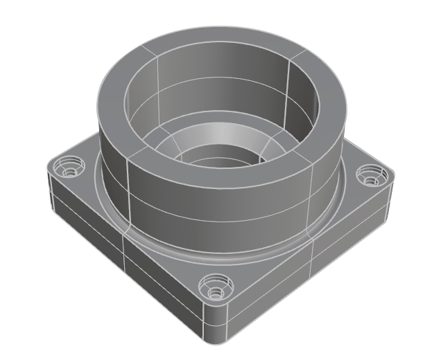
Geringste Abweichung und ein hoch präzises Modell Ihres Teils:
Parametrisches Modell
Ändern Sie Ihr rückentwickeltes Teil in SolidWorks:
STL to STEP eignet sich bestens für folgende Anwendungsbereiche
Die Neuanfertigung von Produkten mit optimierten Verfahren
Zeichnungen handgefertigter Prototypen
Die Dokumentation handgefertigter Zeichnungen
Für die Replikation von Einzelteilen
Für ein Nominal Modell zur Inspektion mit einem 3D-Scan
Für Blaupausen für die staatliche Zertifizierung
Für die Produktanalyse zur Produktoptimierung
Um Änderungen und Korrekturen am Design vornehmen zu können
Zur Erstellung von Formen für alte Teile, über die keine Daten mehr existieren
Starke Software für STL to STEP
Unsere Experten setzen bei Flächenrückführung auf folgende CAD-Software:

Autodesk
Unser Team ist durch Autodesk in der Lage, aus Ihren Rohdaten perfekt funktionierende 3D-CAD’s zu erstellen.

Catia
Unsere Ingenieure nutzen Catia V6, um Stil und Form der Modelle zu optimieren.

Creo
Wir generieren Daten in Creo. Diese bieten wir ihnen im nativen Datenformat als .creo-Dateien an.

Design X
Design X stellt im Bereich Reverse Engineering die wohl wichtigste Software dar. Die Ingenieure von Mako-Technics verwenden bevorzugt Design X für Modellierungen von STL to STEP.

Inventor
Wenden Sie sich jetzt an Mako-Technics, wenn Sie Inventor dafür verwenden möchten, um den 3D-CAD Ihres Produkts zu erstellen und in kürzester Zeit eine optimal funktionierende STP-Datei zu erhalten.

SolidWorks
Unser Team erstellt native SolidWorks-Dateien. Wir bieten diese unseren Kunden im nativen Datenformat als .sw-Datei an.

Siemens NX
Kooperationen- starke Partner


Der Ablauf
Anwendungsgebiete für STL to STEP

Gussteile & Schmiedeteile

Spritzguss

CNC-Bearbeitung

Stanzen & Formen

Blechumformung

Additiver 3D-Druck
Klicken Sie auf die Schaltfläche unten, um STL to STEP Beispiel-Daten herunterzuladen
FAQ zu STL to STEP
Im Folgenden finden Sie die häufig von den Benutzern gestellten Fragen
Unter STL to STEP versteht man die Rekonstruktion von Punktwolken in Flächen für CAD-Software. Es sind zwei verschiedene Dateiformate und die Umwandlung macht die Punktewolken aus bspw. 3D-Scans erst für die Konstruktion verwendbar. Das konvertieren von stl Datein in step Datein ist somit ein notwendiger Schritt für die weitere Bearbeitung.
Das lässt sich pauschal schwer beantworten, es kommt immer auf den jeweiligen Anwendungsfall an. Im Normalfall ist die Umwandlung von STL to STEP mit erheblich niedrigeren Kosten verbunden als die Neukonstruktion eines Produkts. Sprechen Sie uns gerne an, wir unterbreiten ihnen kurzfristig ein Angebot für ihr Projekt und Bauteil.
Hier kann jede CAD-Software eingesetzt werden. In der Regel arbeitet unser Team beim Erstellen angeforderter STEP-Flächen mit Design X.
Wir erstellen hierbei neue Flächen passend zur vorhandenen Punktwolke. Hierdurch wird das gesamte Objekt neu konstruiert.
Hierfür gibt es eine Vielzahl an Gründen. Im Allgemeinen wird durch STL to STEP ein tieferes Verständnis für das jeweilige Produkt und seine Funktionsweise möglich.
Produktionsprozesse lassen sich durch STL to STEP beurteilen und anpassen. Die Bestimmung und Optimierung von Prozessen sind daher klassische Anwendungsgebiete für STL to STEP in der Industrie.
3D-Scanner werfen ein Raster aus weißem Licht oder Laserlinien auf ein Objekt. In einer Sekunde werden hierbei tausende Entfernungsmessungen durchgeführt. Durch den Einsatz von Zielmarken können 3D-Scanner einen Referenzrahmen erstellen.
Sie ermitteln hierdurch, an welcher Stelle sie sich im Vergleich mit dem Objekt im Raum befinden. Alle Messungen werden von ihnen miteinander kombiniert. So wird eine nahtlose Oberfläche des gescannten Objekts erstellt.
STL to STEP als wichtiges Hilfsmittel in der Industrie
Flächenrückführung ist im einfachen Sinne die Fachbezeichnung für den Nachbau dreidimensionaler Punktwolken, die ein Objekt beschreiben. Diese Punktwolken entstehen durch Simulationen oder durch 3D-Scans.
Sie finden häufig im Bereich Werkzeugplanung oder FEM-Berechnungen Anwendung. Durch Reverse Engineering ist Mako-Technics in der Lage, genau diese stl-Daten für eine weitere Verwendung in CAD-Systemen nutzbar zu machen.
Hieraus ergibt sich eine Vielzahl an Möglichkeiten.
Beispiel: Flächenrückführung im Werkzeugbau

Wiki
Über weitere Möglichkeiten und spezielle Besonderheiten möchten wir Sie in Zukunft hier in unserem BLOG informieren. Schauen Sie einfach von Zeit zu Zeit hier wieder mal vorbei.