Use STL TO STEP for Perfect Products

Reverse engineering of 3D Scans

Reverse engineering of Point Clouds

Reverse engineering from STL to STEP
For us, reverse engineering or remodeling means the manual creation of CAD data based on points from a simulation or a 3D scan. This is how we create CAD data that is very important in 3D printing, in the FEM area or in toolmaking.

Details on reverse engineering by Mako GmbH
Remodeling means the creation of new construction data based on point clouds that have been created through simulations or with 3D scans.
The existing geometries are recorded in the point cloud. Each individual element is replicated manually and then merged into a new solid.
Elements can be created with parametric properties. Every step in the construction is recorded in the history.
We create new freeform surfaces separately on the point cloud. Here we select a surface element in such a way that the newly modeled areas correspond to the point cloud with the size of possible precision. In this way, we achieve the smallest possible tolerances.
This approach enables us to achieve the highest level of precision for all areas of industry.
Differentiation between STL and STEP
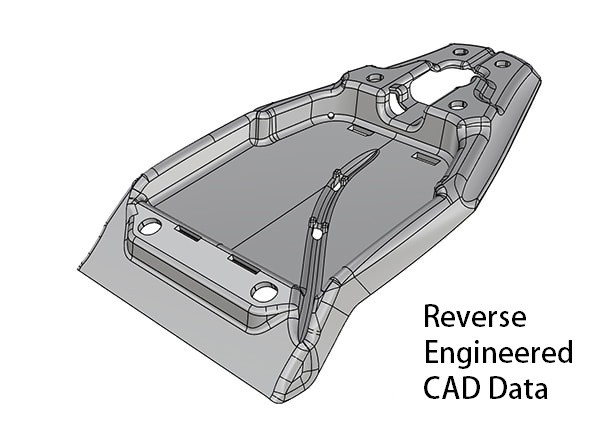
Move the arrows to see the data before and after remodeling
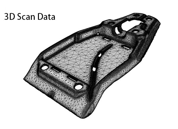
Scan-based files only include cleaning up the scan and optimizing the point cloud. Working on a CAD basis is significantly more time-consuming. Here, CAD sketches and CAD features are created and adapted to the scanned data.
Once the scanned data has been recreated in CAD, we can create the neutral file based on the final CAD geometry. The Mako-Technics experts attach great importance to compliance with German quality standards.
A CAD file contains the actual geometrical features of the scanned part. So a cylinder is a real cylinder. The same applies, of course, to flat surfaces, cones and spheres. This enables you to create and use construction geometries such as planes, axes, and surfaces.
Since this is a real CAD shape, there are also sharp edges on the original part.
Convert your 3D scan data from STL to STEP. Rely on Mako-Technics:
Reverse Engineering Applications

Industrial 3D models

2D drawings

Part models

3D print files and parts
Who is Mako-Technics?
Mako-Technics is a leading brand of Mako GmbH (1998) based in Germany. We offer our customers excellent reverse engineering services worldwide. Exemplary 3D modeling and precise remodeling set us apart.
Excellent employees with great experience, strong technical leadership and strategic partnerships with customers, manufacturers and software developers have brought Mako-Technics steadily growing success for decades.
These foundations enable us to continue to offer first-class STL TO STEP services and to successfully maintain our technological leadership position. Our know-how is your added value. Trust in our experience. Make Mako-Technics your strategic partner.
How can we help you?
Reverse engineering is the fastest and most efficient way to create CAD files of physical objects or parts. With the help of 3D scans, our team generates a point cloud that corresponds to the data of the original.
On this scan, we then construct properties and geometries that are present in the original object. As parametric models, we can create these geometries in any CAD software. We keep an eye out for our customers' requirements.
Our know-how and experience make us your ideal partner. Our most important services in the field of STL to STEP include:

3D scan to CAD
We are experts in remodeling into optimally structured CAD files.

STL to STEP
We will be happy to provide you with a 3D scan of your object. At your request, we can convert this from STL to STEP.
3D Scan to CAD
Scan To CAD is a semi-automated service that converts your 3D scans into editable, design-ready, and professional-grade CAD files. These CAD files are fully editable and designed to work with a number of different CAD software according to your choice.
Our Engineers use the following CAD Software:
Autodesk
We use Autodesk to visualize, simulate, and analyze real-world performance using a digital model in the design process.
SolidWorks
We create native SolidWorks files and offer our customers native data format as *.sw files. The data can directly be opened at customer side.
Catia V6
Mako-Technics uses CATIA V6 to enhance the style and shape of the model. Coherent models are converted to their physical forms.
Design X
If you avail Mako-Technic’s services, we can effortlessly transform your STL 3D scan to STP using Design X. We can recreate complex geometry.
Creo
We generate the files in Creo and offer you native data format as *.creo files. The data can directly be opened at customer side.
Siemens NX
Our engineers can perform back-engineering and return an accurate and precise duplicate by using the robust and efficient Siemens NX.
STL to STEP
Depending on your requirements, we can provide you with two types of models. You decide which of the following models is best suited for your application:
Solid State Model
Smallest deviation and a highly precise model of your part:
Solid modeling gives us the slightest deviation from your original part. We are talking about a highly precise reverse engineering process. Due to its small file size and the neutral CAD, it can be approved for almost any 3D software (IGES, STEP) for all production areas.
By modeling solid surfaces, you create exactly the component that you need for your purpose.
Parametric Model
Change your reverse engineered part in SolidWorks:
STL to STEP does not make sense for parametric models, but if required we will be happy to provide you with parametric models in your desired software. Parametric modeling is perfect for products that are controlled by dimensions.
This approach allows engineers to efficiently and easily create a wide variety of configurations for their designs. The parametric modeling can include pattern instances, wall thicknesses, dimensions, diameters and depths of holes.
STL to STEP is ideally suited for the following areas of application
The manufacture of new products with optimized processes
Drawings of hand-made prototypes
Documentation of handmade drawings
For the replication of individual parts
For a nominal model for inspection with a 3D scan
For blueprints for state certification
For product analysis for product optimization
To be able to make changes and corrections to the design
Used to create shapes for old parts that no longer have data
Strong software for STL to STEP
Our experts use the following CAD software for reverse engineering:

Autodesk
Thanks to Autodesk, our team is able to create perfectly functioning 3D CAD’s from your raw data.

Catia
Our engineers use Catia V6 to optimize the style and shape of the models.

Creo
We generate data in Creo. We offer these in the native data format as .creo files.

Design X
Design X is probably the most important software in the area of reverse engineering. Mako-Technics engineers prefer to use Design X for modeling from STL to STEP.

Inventor
Contact Mako-Technics now if you want to use Inventor to create the 3D CAD of your product and have a perfectly working STP file in no time.

SolidWorks
Our team creates native SolidWorks files. We offer these to our customers in the native data format as .sw files.

Siemens NX
You can provide us with the STL file of your object. Our experienced engineers then carry out the reverse engineering and use Siemens NX to give you a precise duplicate.
Cooperation - Strong Partners
In order to offer our customers the perfect service, we work with partners around the globe. Our partners rely on a large number of scanning devices. For example Shining3D, GOM, CREAFORM, Solutionix, Arten, Keyence, Leica, Farm and many more.
If you are unsure about which scanner to choose, please contact us. We will be happy to help you choose.


Our Process
Our process always begins with the selection of the appropriate CAD software. Mako-Technics then use the software of your choice to transform your source file into high quality and precise CAD data.
We have a team of highly motivated, experienced and qualified engineers at your disposal. The project team determines the details of the process. We agree on the most precise and fastest type of redesign.
Our experience is your added value. You too can trust in our expertise.
Areas of Application for STL to STEP

Castings & forgings

Injection molding

CNC processing

Punching & forming

Sheet metal forming

Additive 3D printing
Click the button below to download STL to STEP sample data
FAQ on STL to STEP
Below are the frequently asked questions by users
STL to STEP is the reconstruction of point clouds in areas for CAD software.
That is difficult to answer across the board, it always depends on the particular application. STL to STEP is normally associated with significantly lower costs than redesigning a product.
Any CAD software can be used here. As a rule, our team works with Design X when creating the requested STEP surfaces.
We create new areas to match the existing point cloud. This redesigns the entire object.
There are a number of reasons for this. In general, STL to STEP enables a deeper understanding of the respective product and how it works. Production processes can be assessed and adjusted using STL to STEP.
The determination and optimization of processes are therefore classic areas of application for STL to STEP in industry.
3D scanners cast a grid of white light or laser lines onto an object. Thousands of distance measurements are carried out in one second. By using target marks, 3D scanners can create a reference frame.
This enables you to determine where they are in comparison with the object in the room. They combine all measurements with one another. This creates a seamless surface of the scanned object.
STL to STEP as an Important tool in Industry
Reverse engineering is, in the simple sense, the technical term for the reproduction of three-dimensional point clouds that describe an object. These point clouds are created through simulations or 3D scans.
They are often used in the area of tool planning or FEM calculations. Through reverse engineering, Mako-Technics is able to make precisely this data usable for further use in CAD systems.
This results in a multitude of possibilities.
Example: Reverse engineering in toolmaking

1. The master model is scanned and rebuilt with reverse engineering as a parametric data set. The designer can continue working with this data immediately.
2. Material flow in tool design is simulated with software. We prepare the result using reverse engineering so that it can be compared directly with the original CAD data set. Minimal deviations are immediately visible and the construction can already be optimized here.
3. Initial samples are measured using a 3D scan. The resulting data can also be used by reverse engineering to further perfect the tool.
Our Blog
In the future, we would like to inform you about further possibilities and special features here in our BLOG. Just stop by here from time to time.